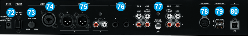
POWER: Use the included power adaptor to connect DJ-808 to a power outlet. Use the Power Switch to turn the unit on and off. Turn on DJ-808 after all input devices have been connected and before you turn on amplifiers. Turn off amplifiers before you turn off the DJ-808
MIC SENS Adjusts the mic input sensitivity.
MIC INPUT. Connect your microphone to this socket using any of three types of plugs (XLR, TRS, phone).
MASTER OUT 1 (L / R) connectors, 2 (L / R) jacks Connect your powered speakers or power amp here. The level of this output is controlled by the MASTER LEVEL knob at the top panel
BOOTH OUT (L / R) jacks These are the output jacks for booth monitoring. The level of this output is controlled by the BOOTH MONITOR knob at the top panel
INPUT (CH 1–CH 4) These sockets input sound to mixer channels 1–4. The CH1 and CH2 inputs support phono input from MM-type cartridges. Set the [INPUT SELECT] switch appropriately for the device you’re connecting.
MIDI OUT This connection outputs MIDI messages such as MIDI clock.
USB HOST These are USB audio input ports. Both ports 3 and 4 can supply USB bus power. For more about devices that can be connected, refer to the Roland website.
USB. This USB connection sends and receives audio and control information from a connected computer.
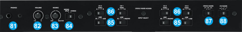
HEADPHONES SOCKET. Connect your 1/4" or 1/8" headphones to this output for cueing and mix monitoring.
HEADPHONES VOLUME. Adjusts the volume level of the headphone output.
HEADPHONES MIXING: Turn to mix between Cue and Program in the Headphone channel. When all the way to the left, only channels routed to Cue will be heard. When all the way to the right, only the Program mix will be heard.
HEADPHONES SPLIT. When this switch is in the ON position, the headphone audio will be "split" such that all channels sent to Cue are mixed to mono and applied to the left headphone channel and the Program mix is mixed to mono and applied to the right channel. When the switch is in the OFF position, Cue and Program audio will be "blended" together.
CROSSFADER ASSIGN: Routes the audio playing on the corresponding channel 1 to 4 to either side of the crossfader (A or B), or bypasses the crossfader and sends the audio directly to the Program Mix (center, THRU).
INPUT SELECT: Select the input source for each mixer channel. CH1, CH2 PC : The sound loaded into VirtualDJ deck 1/2 is the source. Select this if you’re using DVS (Timecodes). LINE : The line level input is the source. PHONO : The phono level (MM type cartridge) input is the source.
CH3, CH4 PC : The sound loaded into VirtualDJ 3/4 deck is the source. Select this if you’re using DVS (Timecodes). LINE : The line level input is the source. USB : The input from the USB HOST port is the source.
CROSSFADER CURVE. Switches the response curve of the cross fader.
CH FADER CURVE: Switches the response curve of the channel faders.