POWER ON/OFF: Use the Power Switch to turn the unit on and off. Turn on unit after all input devices have been connected and before you turn on amplifiers. Turn off amplifiers before you turn off unit
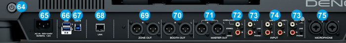
POWER IN: Use the included AC cable to connect Prime 4 to a power outlet. While the power is switched off, plug the cable into unit first, and then plug the cable into a power outlet.
USB 3/4. Connect other USB devices in the ports of this USB hub. Keep in mind that the devices connected to these ports will not be available as computer devices, when the Prime 4 is on Standalone (Engine) mode.
USB B. Use the provided USB type B to type A cable to connect the unit with a USB port of a computer. This USB connection sends and receives audio and control information from a connected computer.
LINK.Not used in VirtualDJ
ZONE OUT (XLR): Use XLR cables to connect this output to a separate PA system or room. The level of this output is controlled by the Zone section on the top-right panel.
BOOTH OUT (XLR): Use XLR cables to connect this output to a booth monitoring system. The level of this output is controlled by the Booth section on the top panel.
MASTER OUT (Balanced - XLR): Connect this low-impedance XLR output to a PA system or powered monitors. The level of this output is controlled with the Master Level knob on the top panel.
MASTER OUT 2 (RCA): Use standard RCA cables to connect this output to a speaker or amplifier system. The level of this output is controlled by the Master Level knob on the top panel.
LINE 3/4 INPUTS. Connect your audio sources to these inputs. These 2 inputs can accept both line and phono-level signals and can be used for DVS as well (see Inputs & Recording ). Use the USB-LN3/LN4 switches at the front panel to send the audio signal of these Inputs to Mixer Channel 3/4 respectively.
LINE 1/2 INPUTS. Connect your audio sources to these inputs. These 2 inputs cannot accept phono-level signals and cannot be used for DVS . Use the USB-LN1/LN2 switches at the front panel to send the audio signal of these Inputs to Mixer Channel 1/2 respectively.
MIC 1/2 Connect up to 2 microphones to these sockets, using a 1/4" cable or XLR. The audio signals of these inputs are routed directly to the Program Mix and Cue Mix. The level of the Microphone Inputs are controlled from the top-left panel
Denon DJ Prime 4 - Front panel
HEADPHONES SOCKET. Connect your 1/4" or 1/8" headphones to this output for cueing and mix monitoring.
USB-LN1 to LN4 . Use these switches to select which source will be routed to each Mixer Channel. Set to USB to route a VirtualDJ Deck to a Prime 4 Mixer channel. Set to LN1/LN4 to route the signal of the auxiliary source connected to the rear Inputs to a Mixer Channel. VirtualDJ decks will be muted in this case. The LN3/LN4 need to be set to USB if used for DVS. See Inputs & Recording
FADER START LEFT. When set to ON, the tracks loaded to Decks 1 and 3 (Left Decks) will start plying as soon as their Volume faders is moved from low position towards up or the Crossfader moved from right to left side.
XFADER CURVE. Adjusts the slope of the crossfader curve. Turn the knob to the left for a smooth fade (mixing) or to the right for a sharp cut (scratching). The center position is a typical setting for club performances.
FADER START RIGHT. When set to ON, the tracks loaded to Decks 2 and 4 (Right Decks) will start plying as soon as their Volume faders is moved from low position towards up or the Crossfader moved from left to right side.